Bitmain S17/T17+ Bitcoin Miner Repair Guide I
This post introduces S17+ bitcoin miner‘s operation structure and current and signal direction of which need to be understood in the maintenance process, as well as listing the function description of some main components.
Last update:2022-12-01 21:08 Tags:Miner Maintenance ResourcesAntminer S17 Miner Repair Language: Platform:No restriction
0 Already downloaded Mobile view
Overall Antminer S17 Principle of Operation
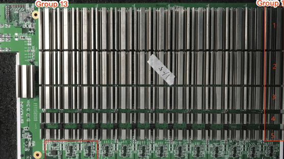
1. Working structure of S17+ hashing board:
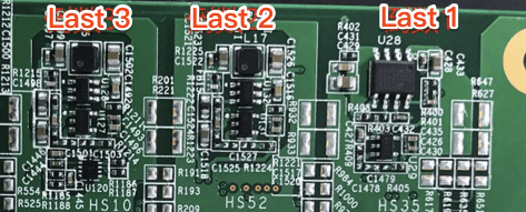
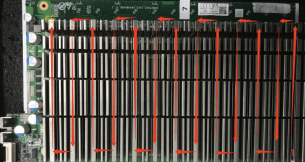
The hashing board consists of 65 BM1397 chips and is divided into 13 groups. Each group consists of 5 IC chips. The BM1397 chip used in the S17+ hashing board works
The voltage is 1.5V; The first reciprocal is 24.5V output by the booster circuit U6 to supply power to LDO and output 1.8V, and the second and third groups are 24.5V output to DCDC
The power supply output is 1.8V, and the other groups are provided by 21V partial voltage through DCDC. All 0.8V is supplied by 1.8V from the local domain via LDO output. Such as
As shown in Figure 4-1:
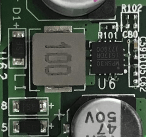
2. Boost circuit of S17+ hashing board:
The boost voltage is from 21V to 24.5V, as shown in Figure 4-2:
3. Signal direction of S17+ chip:
3.1. CLK (XIN) signal direction: generated by Y1 25M crystal oscillator, transmitted from No. 01 chip to No. 65 chip; When calculating, the voltage is 1.45-
1.65V (oscilloscope) Multimeter measurement is about 0.7-0.9V.
3.2 TX (CI, CO) signal flow direction: from the IO port 7 pin (3.3V) through the level conversion IC U2, and then from the 01 chip to the 65 core
Chip transmission; The voltage is 0V when I/O cable is not inserted, and the voltage is 1.8V during calculation.
3.3 RX (RI, RO) signal direction: from No. 65 chip to No. 01 chip, return to the 8th pin of signal line terminal through U1 to return to the control board;
When I/O signal is not inserted, the voltage is 0.3V, and the voltage is 1.8V during calculation.
3.4 BO (BI, BO) signal direction: from No. 01 chip to No. 65; A multimeter is used to measure 0V.
3.5 RST signal direction: input from IO port 3, and then transfer from chip 01 to chip 65; No IO signal plugged in, 0V in standby mode, go
So this is 1.8V.
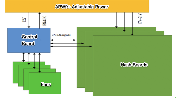
4. Overall architecture:
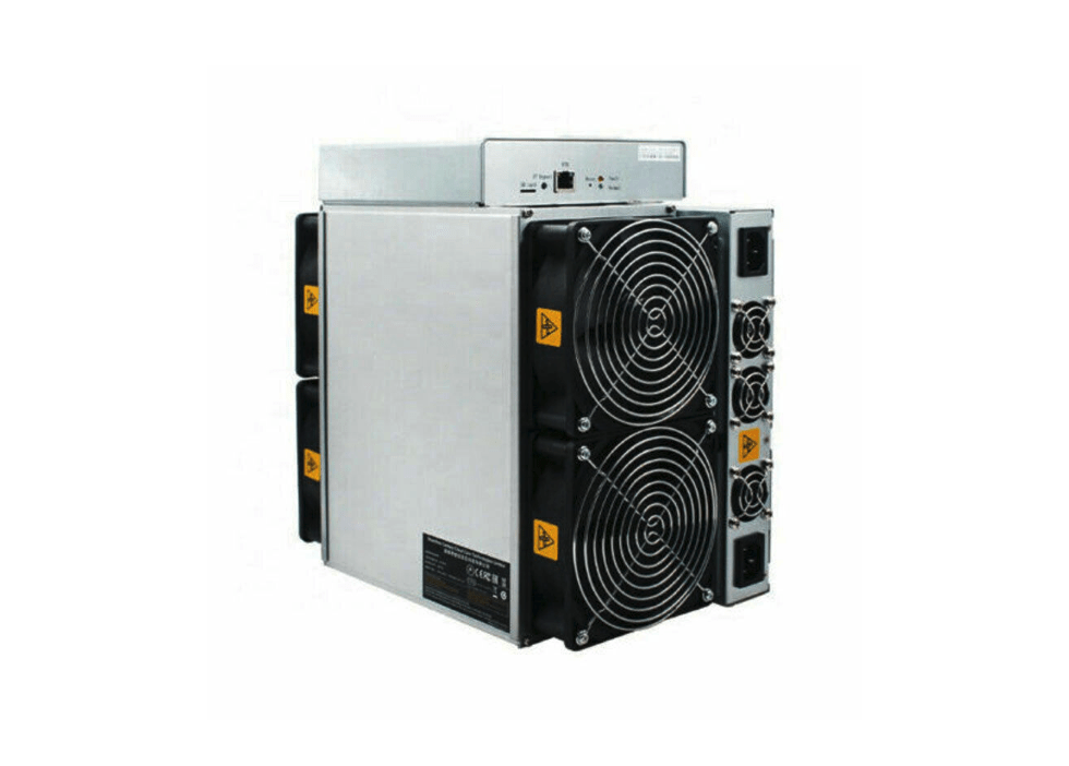
The netcol8000-C consists of three hashing boards, one control board, APW9+ power supply, and four cooling fans, as shown in Figure 4-4.
( ※ Note ※ : The content of this post is mainly sourced from Bitmain technical documents, and the copyright is owned by Bitmain. This post is only for the purpose of mutual communication and learning. if there is any infringement, please contact the webmaster for informing the author of deletion immediately.)
Related Resources